
Setup #2
12-01-08 update
Recent experiment Results10/12
Related cap-plate experiments 2011 on youtube
If you have not yet seen the slideshow of images here is the link to one of several under the same username.
From the CRT experiment results i've seen some of the most detailed features in the form of craters, crater-chains and trenches but without a depth of material sufficient to create walls I was left unsatisfied of the full scope of what information could be yeilded from these experiments. In the following paragraphs, If you find errors in my explanation, i hope you'll inform me with corrections.
|
|
CRT screens are essentially a plate capacitor that is bombarded by an electron gun at the back of the tube. Charge is established on the interior surface and without special consideration built into the device the screens would be highly charged on their exterior surface. The type of CRT used in the first experiments was quite active. It attracted allot of dust and if an object got too close the surface would discharge with a loud pop. I learned this while intending to clean the dust from the surface, and what a surprise it was.
To attempt getting similar sesults with a stronger spark is the intention of the cap-plate experiment. Determining the force requirements involved in forming the various features seen on planetary bodies will help understand the age of bodies scared with craters and other features. Some of the features under consideration would involve discharge energies of incredible ferocity and others may be more subdued by comparrison and occuring on a regular basis giving us the fresh-looking features seen on many bodies. These are the features these experiments are intend to focus upon and hopefully identify in contrast to the others.
|
|
 |
Through the work of many researchers over the years, the electric mechanism has been suggested and validated through experiments. Amoung those researchers, the one that got me going on this line of thinking is Wal Thornhill. His work with high energy discharges is well established and my hope is to complement that perspective and emphasize lower energy aspect, because this activity may be what we will be seeing in the present as we get a closer look on mars and elsewhere. In later years, the experimente CJ Ransom showed me his results -and in a limited way, discussed some details. Other contributors can be seen at the thunderbolts forum thread on CRT experiments, there are too many to mention here.
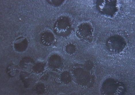
From the images of the CRT experiment one of the most outstanding feature associated with crater-like patterns is the concentration of material at the perimeter. Next to that is the way crater chains form, not overlapping like a weld bead but connected in adjacent fashion with partial-circular features being subsequent in their occurance aside completely round craters. Counter-intuitive in how i described this in discussions back in 2006 and even before in web posts. These details can be clearly observed during their formation by low energy discharges from the CRT to a probe.
I'm crazy about crater chains.
 |
 |
This image is from cap-plate version of experiment. Here the craters in the center are in deep material and formed without the probe reaching the surface. |  This is from the single-plate version. The probe had to be held in the material in the central area of the mound in order to coax an arc. The two large craters were from numerous arcs to the plate, all remaining in the center of the cleared area. |
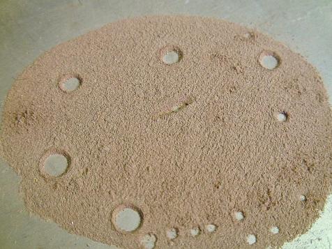 This is a new setup different than was used for the pictures above. The intention is to attempt to remove the air barrier to see if the arc will reach further and also to see if the material might behave differently. The probe height is just a bit more that was needed for formation of the current craters. An important detail is that the arc was targeted on the center of the crater. |
 |
 This image is an intermediate
capture which shows a stage in the progression of this discharge location.
I was going to stop here but then the coaxing came saying i'd like the
results if i went longer.
This image is an intermediate
capture which shows a stage in the progression of this discharge location.
I was going to stop here but then the coaxing came saying i'd like the
results if i went longer.
A note about the probe location; While suction was put on the chamber the probe would move forward and down so its current location is somewhat missleading. The adjacent craters were made individually at two separate phases of the experiment.
The halfpipe feature
in the top center is
from the edge of a quarter.
The
characteristics of the resulting image suggested to me that the crater-like
features of the CRT experiments might differ somewhat if a sustained or
repeated arc were to occur. If non visible discharges have the same effect
as visible ones then this supposition may not be warranted. There were
numerous discharges observed in the CRT runs which were stationary and
multiple with one important detail to realize, the repeated discharges were
much smaller than the initial one and sometimes left tiny round features
inside the larger. The first discharge was a transfer of material to the
probe accompanied by a concentration of material around the rim. The
subsequent ones were real hard to coax and observe, but from the pattern
left, it seemed to focus between the rim and the center. This may explain
an interior concentration
seen in many features and in this
electric wind experiment.
There may be more similarity between these two experiments than I might've
thought. In CRT runs, when the initial discharge was adjacent to others
it would not be a whole circle unless it was in a far seperated time frame
as the others.
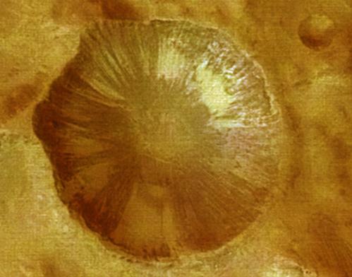
 The
time frame detail is similar to the one in the current experiment which
resulted in this superimposed feature, as described by Wal Thornhill.
The
time frame detail is similar to the one in the current experiment which
resulted in this superimposed feature, as described by Wal Thornhill.
A NASA image, similar to right image, can be found here in an article at one blog of the Thunderbolts.info team.
The
repeated arc discharges that formed the central feature stayed within the
central part of the exposed plate. You will see in the image above the distance between the adjacent, previous, craters. The halfpipe,
a rectangular impression, has by now been partly erroded by the arc which formed the superimposed crater.
Oh what we can learn from a pile of dirt.
12/01/2008 update
A note about the probe location; While suction was put on the chamber
the probe would move forward and down so its current location is somewhat
missleading. The adjacent craters were made individually at two separate
phases of the experiment. Also, In almost every location material would move to the probe before the arc
occurred. You'll see some traces of that attraction in other images around
the edges of the dirt pile.
|
I am begining to suspect the need for the allowance of charge saturation time. As mentioned above, this was practiced in the CRT experiments and the results seemed to be a very reactive surface. Far different than this cap-plate setup where multiple arcs are required to move the material gradually. A dramatic contrast to the CRT surface's material displacement. A question is raised in my mind as i see the limitations of an arc, even in shallow material a single arc leaves a much smaller feature than was made with a single arc discharge (non visible however) to the surface of a dust covered CRT. There are two detail to consider in this comparrison; the size of the probe (my finger compared to the tip of a voltmeter probe) and the amount of energy being sent to the surface of the plate capacitor. This detail will be addressed after looking into probe considerations. I'd use my finger for this cap-plate experiment but the jolt is a bit intense.
|
 The probe movement during evacuation of the chamber was a problem that showed up as elongated craters. The solution is a different chamber. I was able to acheive 16 inches of vacuum with this one. I'm still pondering the results at these lower pressures so another picture is all I've got for now. The feature under the probe in image dsc200 was made with about 10 in vac. The lobes were made by swinging the probe.
Find it here
The probe movement during evacuation of the chamber was a problem that showed up as elongated craters. The solution is a different chamber. I was able to acheive 16 inches of vacuum with this one. I'm still pondering the results at these lower pressures so another picture is all I've got for now. The feature under the probe in image dsc200 was made with about 10 in vac. The lobes were made by swinging the probe.
Find it here
More to be added later
www.electric-spark-scars.com

 replicating them in deeper material while maintaining some capacitor characteristics to the surface, and with whatever arc-energy necessary to create the detail that is captured by space probes around numerous celestial bodies. None more clearly emphasizes this than the stereo images from the European Space Agency.
 This setup of the Capacitor plate experiment has a larger surface area of the positively charged lower plate and the results are somewhat different in the characteristics of the arc. The intensity of the arc seems to have increased which may allow for layers of material or at least greater depths. The behavior of the arc has also changed.